Faking an IR signal with an Arduino
July 5, 2022TL;DR: This is an instruction how to emulate the signals produced by an IR receiver with an Arduino.
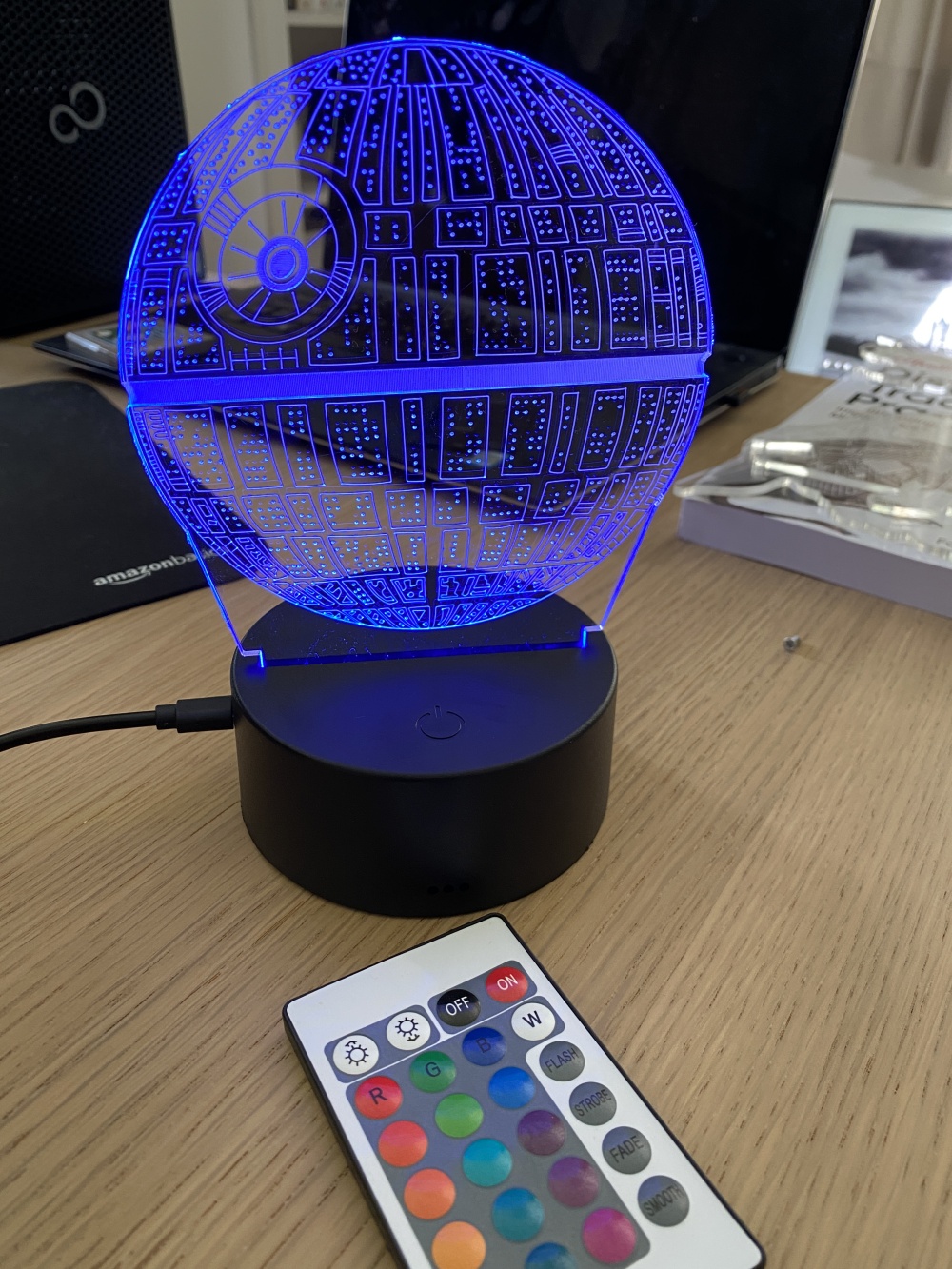
For the last father's day, my wife got me this Star Wars-themed acrylic LED light.
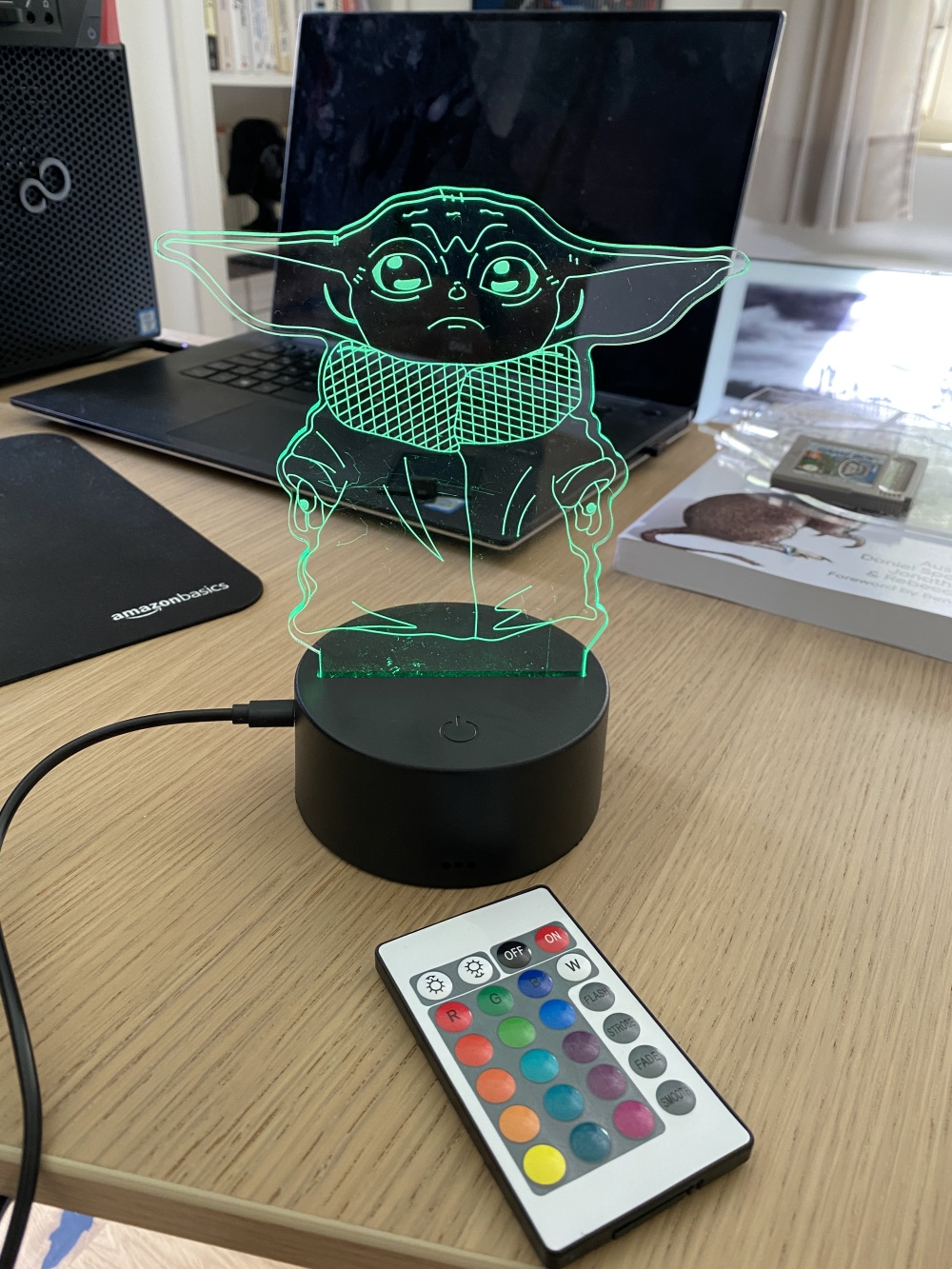
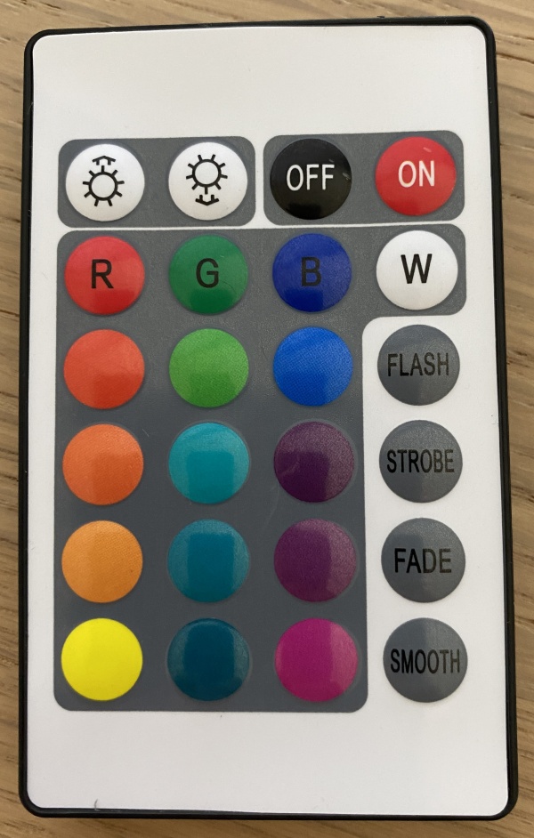
It comes with replaceable acrylic plates (Yoda, the Death Star, the Millenium Falcon, and Boba Fett) and the typical LED IR remote control.
While the interaction with LED remote controls is fun on the first day, I'm generally not a big fan of those.
- They all look the same and you never know which device they are for.
- They get misplaced easily, rendering their controlled devices unusable.
- I rather integrate all lighting into home automation routines (e.g. "turn on after sunset").
So I decided to hack the lamp and replace the IR control with something else.
Getting rid of the IR remote
The simplest way would have been adding an IR sender to an Arduino and just sending the remote control codes. There are plenty of projects out there (e.g. this one) doing exactly that.
However, I was interested in going a level deeper and fully replacing the IR receiver.
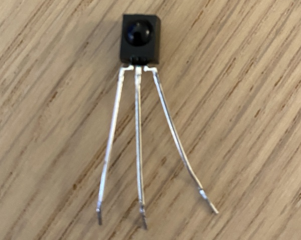
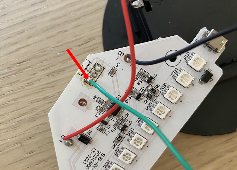
So I unsoldered the IR receiver component.
Then connected an Arduino's output pin to where the IR signal line was before.
Replicating the IR protocol
Now I had to produce the same signal with the Arduino that the IR receiver had generated before. With a bit of Googling, I learned about the NEC IR Protocol is the typical default for such devices. Fortunately, it is relatively simple:
The signal is high by default (when nothing is sent).
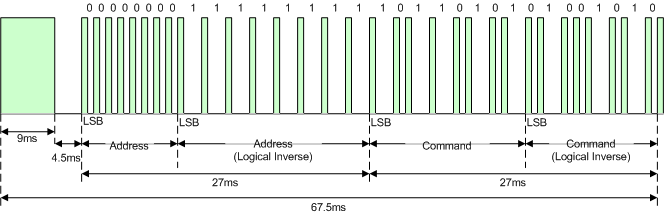
If a command is sent, a frame looks like this:
- 9000 µs low.
- 4500 µs high.
- The device address byte (typically 0).
- The device address byte bit-wise inverted (... or not ... let's put a pin in that!).
- The actual command byte (i.e. the button pressed on the remote).
- The command byte bit-wise inverted.
The individual bytes are sent LSB (least significant bit) first and the bits are encoded like this:
- 0 bit: 560 µs low, 560 µs high
- 1 bit: 560 µs low, 1690 µs high
The frame ends with another 560 µs low signal.
Here's a visualization of such a frame (found here):
I also found an existing Arduino implementation of this protocol and a list of the alleged (😬!) IR control codes.
Troubleshooting
It would have been too easy if this had worked immediately - of course, it did not.

So I spent a couple of hours tracking down the problem.
- I checked the Arduino code again and again (timing, bit-shifting, ...).
- I added a level shifter from 5V to 3.3V to my circuit (since the IR receiver was originally operating on 3.3V).
- I found this simple Arduino based logic analyzer and compared "IR mode" to "Arduino mode". With this I actually could (should) have figured out the problem. Turns out, I had not gone deep enough and only gave the signal that I created a quick sanity check.
Finally, using the Arduino IRremote library put me back on the right track. I examined the actual data sent by the IR remote using the MinimalReceiver sample, that decodes the NEC protocol.
It turned out that I had relied too much on the resources that I had found before.
Looking at the output, that this sample produced ...
...
A=0xEF00 C=0x4 R=0
A=0xEF00 C=0x8 R=0
A=0xEF00 C=0x8 R=0
A=0xEF00 C=0x9 R=0
A=0xEF00 C=0x9 R=0
A=0xEF00 C=0x6 R=0
...
... I realized that neither the address nor the command were in the format that I had expected all the time.
- The device address was different:
0x00followed by0xEF(instead of the bit-wise inversion!). - The control codes simply ranged from
0(the top-left button on the remote) to23(bottom-right).- OFF would be
2. - ON would be
3. - Red would be
4. - Green would be
5. - Blue would be
6. - ...
- OFF would be
So, I made these small adaptions to my Arduino sketch and suddenly it was working 🤩!
Below is the full sample code.
- It simulates the ON command in the
setupfunction, making sure the LED strip is on. - Then, it alternates between yellow and purple periodically in the
loopfunction.
#define DATA_PIN 12

#define DELAY_LEAD  9000
#define DELAY_SPACE 4500
#define DELAY_BURST  560
#define DELAY_0 DELAY_BURST
#define DELAY_1 1690


void send_0()
{
  digitalWrite(DATA_PIN, LOW);
  delayMicroseconds(DELAY_BURST);
  digitalWrite(DATA_PIN, HIGH);
  delayMicroseconds(DELAY_0);
}

void send_1()
{
  digitalWrite(DATA_PIN, LOW);
  delayMicroseconds(DELAY_BURST);
  digitalWrite(DATA_PIN, HIGH);
  delayMicroseconds(DELAY_1);
}

void send_byte(uint8_t c)
{
  for (int bits = 0; bits < 8; bits++)
  {
    if (c & (1 << bits))
    {
      send_1();
    }
    else
    {
      send_0();
    }
  }
}

void send(uint8_t code)
{
  digitalWrite(DATA_PIN, LOW);
  delayMicroseconds(DELAY_LEAD);
  digitalWrite(DATA_PIN, HIGH);
  delayMicroseconds(DELAY_SPACE);

  send_byte(0x00);
  send_byte(0xEF);

  send_byte(code);
  send_byte(~code);

  digitalWrite(DATA_PIN, LOW);
  delayMicroseconds(DELAY_BURST);

  digitalWrite(DATA_PIN, HIGH);
  delay(500);
}

void setup()
{
  pinMode(DATA_PIN, OUTPUT);
  digitalWrite(DATA_PIN, HIGH);
  delay(100);

  send(0x3);  // ON
}

void loop()
{
  send(20);  // Yellow
  send(22);  // Purple
}
And here's the project in action.