Making a Volume Control for your PC
October 7, 2018Why?
A volume control for my PC? Why would I need that? Well, as it turns out you probably won't. Me, on the other hand, I am using a mechanical keyboard that lacks any kind of media keys - thus, no o volume control either. I havealready blogged about a solution involving shortcut keys, scripts and additional software (e.g. AutoHotKey) but I was not 100% happy with that solution, since it was Windows-only, also I kept forgetting those shortcuts and most importantly I really wanted a physical interface to control my PC's volume.
I wanted a physical interface for controlling the volume on my PC.
What?
This was the list of required components I came up with for this project:
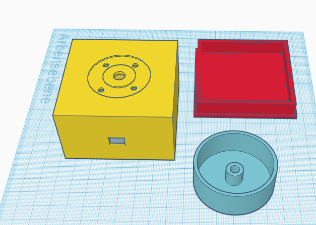
The Case
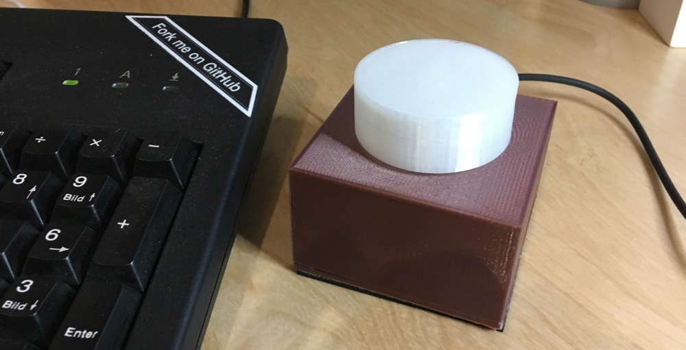
The need for a case usually means 3D printing for me. I shortly considered making the case out of wood to give it a more classy and distinguished look, but then I decided against it. 3D printing would allow for quicker prototypes and iterations. Maybe I will build the box out of wood some time in the future, now that I have figured out the final design (narrator: "he probably won't").
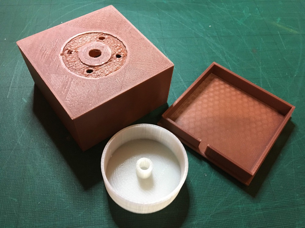
For the knob, I went with a translucent filament to enable some cool visual feedback (see below) when interacting with the volume control.
I used Tinkercad for modelling the case and the knob.
The Tinkercad model is available here or you can also download the exported STL files for 3D printing directly on Thingiverse.
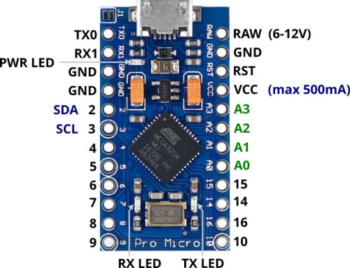
Arduino Pro Micro
I specifically went for an Arduino Pro Micro in this case because it offers a feature, that e.g. an Arduino Nano or Mini will not provide out of the box. This Arduino runs an ATmega32U4 processor which can serve as a USB HID (Keyboard or Mouse) device. That way we can easily emulate a keyboard, and with the proper library send media key commands that will set the PC's volume accordingly.
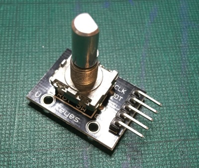
Rotary Encoder
As opposed to a Potentiometer, which reports absolute values and is limited in either turning direction, a Rotary Encoder reports the relative change and can be turned infinitely in each direction. This matches the volume control use case perfectly, since a keyboard's media keys neither "know" about the volume's absolute value, but only send commands to increase or decrease it.
Additionally, this very Rotary Encoder can be clicked and serves as a button, which will be used as a mute toggle switch.
Neopixel Ring
To provide visual feedback on interaction with the volume control, an Adafruit Neopixel Ring with 12 RGB LEDs will be used.
![]()
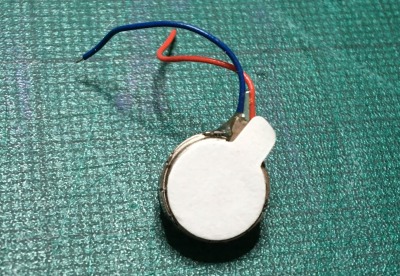
Vibra Motor
This part can probably be considered optional, but adding haptic feedback through a vibrating mini motor disc adds a nice, professional touch to this volume control device.
The Usual
Of course a couple of the "usual suspects" will be required as well:
- 1kΩ resistor
- 470Ω resistor
- 1000µF electrolytic capacitor
- 0.1µF ceramic capacitor
- 1N4007 diode
- BC547C transistor
- circuit board
- cables
How?
Having a vision and all components in place, these were are the individual steps necessary for putting this project together.
Keyboard Emulation
Although the Arduino API provides a Keyboard class out of the box, this is not what would do the trick for this project. The problem with this built-in keyboard emulation, is that it won't allow for sending extended key codes, which is exactly what we need in this case.
Fortunately, there's HID - a great open source library on GitHub, that supports emulation of media keys perfectly well. Also, it is really simple to use. The class Consumer only needs to be initialized and can then send arbitrary key codes using its begin method. The following code illustrates that.
#include <HID-Project.h>

void setup() {
  // Initialize Consumer API
  Consumer.begin();

  // Send media key codes
  Consumer.write(MEDIA_VOL_UP);
  Consumer.write(MEDIA_VOL_DOWN);
  Consumer.write(MEDIA_VOL_MUTE);
}
Mechanical Input
The most important piece of this circuit is the rotary encoder, since it provides the data whether volume needs to go up, down or has to be muted. Following schematic shows how the rotary encoder and the Arduino ware wired.
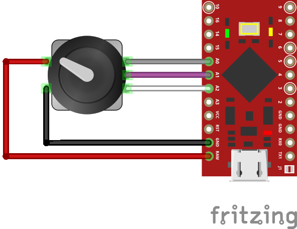
We could go through the effort of reading and evaluating the input data from the rotary encoder ourselves, but yet again, there's a great library that provides that functionality already. The ClickEncoder library makes it easy to attach an interrupt service routine (ISR) to a timer which periodically updates the current rotary encoder state. We could also do this "manually" in the main loop, but this way it is much more efficient and easy to handle. The following code fragment shows how to set that timer up and retrieve rotation and button state information from the rotary encoder.
#include <ClickEncoder.h>
#include <TimerOne.h>

ClickEncoder encoder(A1, A0, A2);

void timerIsr() {
  encoder.service();
}

void setup() {
  Timer1.initialize(1000);
  Timer1.attachInterrupt(timerIsr);
}

void loop() {
  // Get rotation value
  int16_t current = encoder.getValue();

  // Get button state
  ClickEncoder::Button b = encoder.getButton();
  if (b != ClickEncoder::Open) {
    // ...
  }
  // ...
}
Visual Feedback
With each turn of the rotary knob, we want to provide visual information on the volume change.
- Green: Volume Up
- Red: Volume Down
- Blue: Mute On /Off
The following schematic shows how the NeoPixel ring needs to be connected to the Arduino Pro Micro. Best practice is to put a resistor (e.g. 470Ω) on the data line to protect the LED strip and to use a 1000µF electrolytic capacitor.
![]()
Following code fragment shows how to initialize and use the NeoPixel strip using Adafruit's library.
#include <Adafruit_NeoPixel.h>

#define LIGHT_PIN    10
#define VIBRA_PIN    16

Adafruit_NeoPixel strip(NR_OF_PIXELS, LIGHT_PIN, NEO_GRB + NEO_KHZ800);

void setup() {
  // Initialize the LED strip.
  strip.begin();

  // Set all pixels to green
  const uint32_t green = strip.Color(0, 255, 0);
  for (uint16_t i = 0; i < strip.numPixels(); i++) {
      strip.setPixelColor(i, green);
  }
  strip.show();
  //...
}
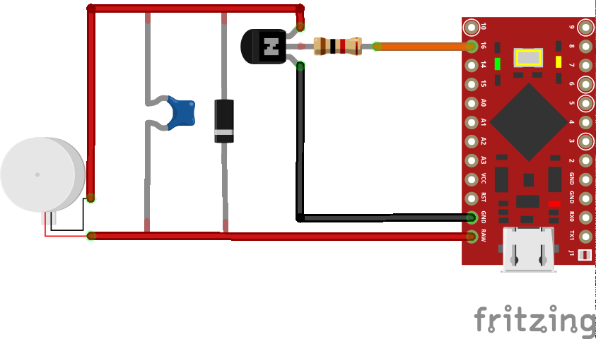
Haptic Feedback
The haptic feedback provided by a small vibrating mini motor disc is wired in the following way. Instead of connecting an output pin of the Arduino directly to the motor, we use a circuit that consists of a capacitor, diode and transistor to protect the sensitive Arduino pins from currents that may be produced in the motor. Whenever we are dealing with any kinds of motors, a protective circuit is the way to go.
Contrary to this slightly complicated circuit, the code for turning the motor on or off is trivial.
#define VIBRA_PIN 16
// Vibra on
digitalWrite(VIBRA_PIN, HIGH);
// Vibra off
digitalWrite(VIBRA_PIN, LOW);
Putting It All Together
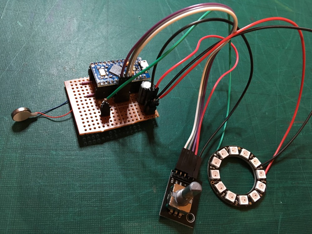
That's all there is for our volume control. All the circuits put together, look like this.
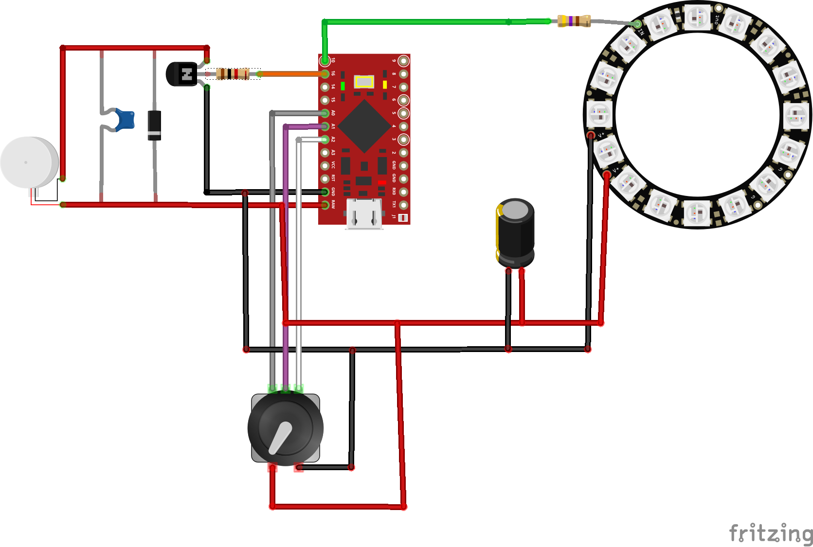
Or like this in the real world.
The Code
Here's the whole code for this volume control at the time this blog post was created. Very conveniently, this volume control's "firmware" can be updated any time since it's connected to my PC through USB anyway.
In the same fashion as the above individual circuits put together, the firmware for the volume control is also a union of the code snippets shown already. At its heart, this code deals with the current value from the ClickEncoder instance and stores it in a helper structure `` that associates a time stamp with the value. That way, we can easily check what changed and also calculate an intensity (how much did it change?). This intensity is then used for setting the LEDs brightness (strip.setBrightness) when changing the color.
#include <Adafruit_NeoPixel.h>
#include <ClickEncoder.h>
#include <TimerOne.h>
#include <HID-Project.h>

template<typename T>
struct TimeStampedValue {
  explicit TimeStampedValue(T value) : _value(value), _timeStamp(0) {}
  void set(const T& value) { _value = value; touch(); }
  operator const T&() const { return _value; }
  void touch() { _timeStamp = millis(); }
  unsigned long getTimeStamp() const { return _timeStamp; }

private:
  T _value;
  unsigned long _timeStamp;
};


#define LIGHT_PIN    10
#define VIBRA_PIN    16
#define NR_OF_PIXELS 12

#define TIMEOUT_VIBRA_MS   30
#define TIMEOUT_LIGHTS_MS 600

Adafruit_NeoPixel strip(NR_OF_PIXELS, LIGHT_PIN, NEO_GRB + NEO_KHZ800);
const uint32_t RED   = strip.Color(255,   0,   0);
const uint32_t GREEN = strip.Color(  0, 255,   0);
const uint32_t BLUE  = strip.Color(  0,   0, 255);
const uint32_t BLACK = 0;

ClickEncoder encoder(A1, A0, A2);
TimeStampedValue<int16_t> value(0);
int16_t current = 0;
int16_t intensity = 0;

void timerIsr() {
  encoder.service();
}

void setup() {
  Serial.begin(9600);

  strip.begin();
  strip.show();

  pinMode(VIBRA_PIN, OUTPUT);

  Timer1.initialize(1000);
  Timer1.attachInterrupt(timerIsr);

  Consumer.begin();
}

void loop() {
  current += encoder.getValue();
  auto diff = current - value;
  if (diff != 0) {
    //Serial.print("Encoder Diff: ");
    //Serial.println(diff);

    if (diff < 0) {
      intensity = max(1, min(intensity + 1, 10));
      volumeChange(MEDIA_VOL_UP, GREEN);
    }
    else {
      intensity = min(-1, max(intensity - 1, -10));
      volumeChange(MEDIA_VOL_DOWN, RED);
    }
    Serial.println(intensity);
    value.set(current);
  }

  ClickEncoder::Button b = encoder.getButton();
  if (b != ClickEncoder::Open) {
    Serial.println("Button");
    switch (b) {
      case ClickEncoder::Clicked:
        intensity = 9;
        volumeChange(MEDIA_VOL_MUTE, BLUE);
        value.touch();
        break;
    }
  }
  else {
    //
    // Turn off LEDs / vibra after certain time of inactivity
    //
    if (millis() - value.getTimeStamp() > TIMEOUT_VIBRA_MS) {
      digitalWrite(VIBRA_PIN, LOW);
    }
    if (millis() - value.getTimeStamp() > TIMEOUT_LIGHTS_MS) {
      setColor(BLACK);
      intensity = 0;
    }
  }
}

void volumeChange(uint16_t key, uint32_t color) {
  digitalWrite(VIBRA_PIN, HIGH);
  setColor(color);
  Consumer.write(key);
}


void setColor(uint32_t c) {
  strip.setBrightness(abs(intensity) * 255 / 10);
  for (uint16_t i = 0; i < strip.numPixels(); i++) {
      strip.setPixelColor(i, c);
  }
  strip.show();
}
And Action!
